Organization
Basic information
Official name
Press-in Technology R&D Center, GIKEN LTD.
Date of Establishment
December 1, 2024
Address
2246-3 Daito, Akaoka, Konan City, Kochi, Japan (In RED HILL 1967, GIKEN LTD.)
3948-1 Nunoshida, Kochi City, Kochi, Japan (In Kochi Head Office, GIKEN LTD.)
16F Ariake Central Tower, 3-7-18 Ariake, Koto Ward, Tokyo, Japan (In Tokyo Head Office, GIKEN LTD.)
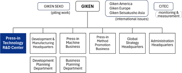
Position of R&D Center in GIKEN Group
Our center is part of GIKEN LTD. and collaborates closely with other departments within the company. This enables us to address a wide range of challenges from diverse perspectives.
Facilities & apparatus
Test Fields
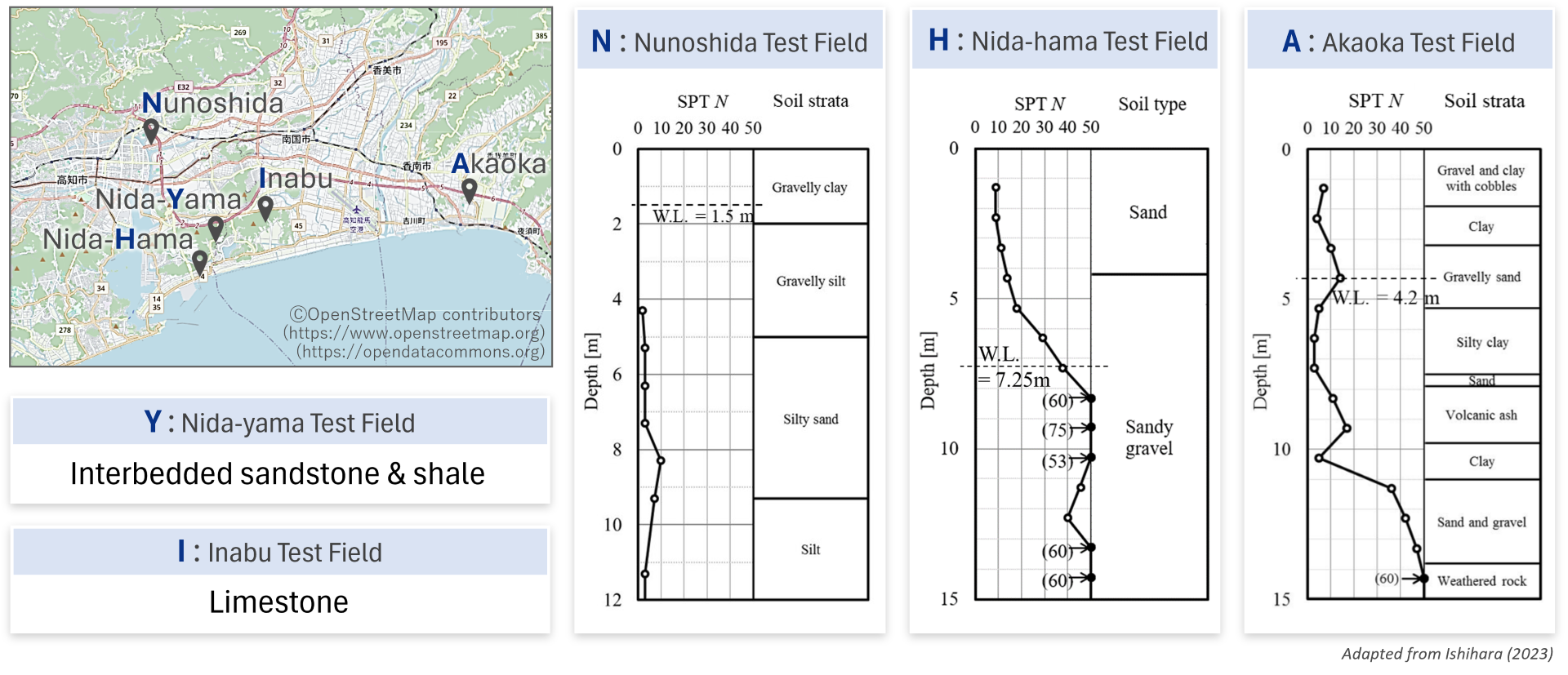
For full-scale field experiments, we utilize several test fields operated by GIKEN. These include the Kochi Headquarters Test Field, characterized by soft alluvial silt and sand; Nida Test Field No. 1 (Nida-hama), featuring dense sand and sand–gravel layers; Akaoka Test Field, consisting of soft alluvial clay and silt containing gravels, underlain by sand–gravel and rock layers; Nida Test Field No. 2 (Nida-yama), with interbedded sandstone and shale; and Inabu Test Field, which is underlain by limestone.
We also operated the Takasu Test Field in the past, but it is no longer in use.
Reference
Ishihara, Y. 2023. Use of press-in piling data for estimating subsurface information and pile performance. Doctoral Thesis, University of Tokyo, 421p.
Liquefaction Experimental Apparatus
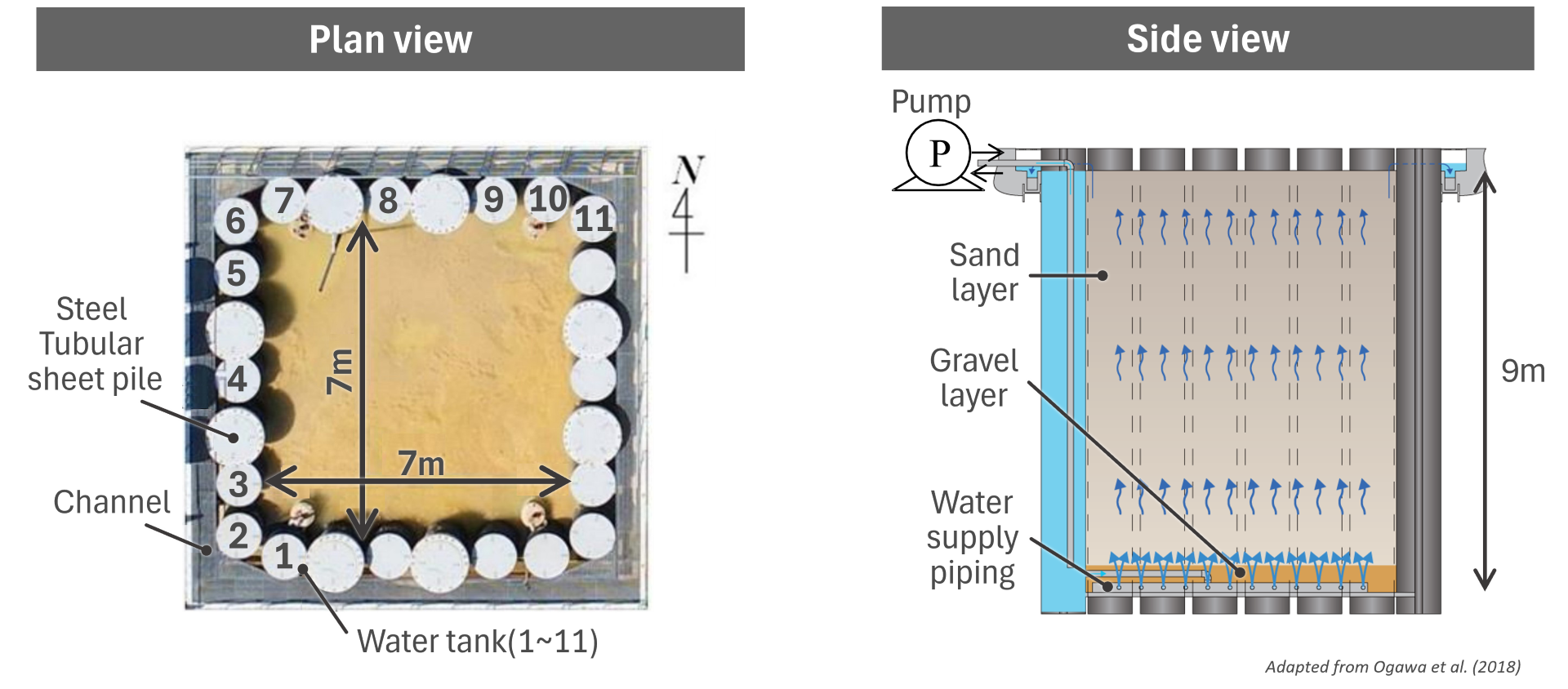
The Liquefaction Experimental Apparatus is a large-scale soil tank equipped with a water supply system at its base. An artificial model ground can be prepared within the tank, which has internal dimensions of 7 m by 7 m in plan and a depth of 9 m.
By controlling the flow rate of water supplied from the bottom, upward seepage forces are induced within the model ground, allowing the effective stress to be reduced and maintained at a constant level. This enables the simulation of a liquefied state for a specified duration (e.g., approximately 30 minutes). Furthermore, by increasing the water flow rate sufficiently, the model ground can be reconditioned for subsequent experiments.
Further details can be found in Ogawa et al. (2018).
Reference
Ogawa, N., Ishihara, Y., Ono, K. and Hamada, M. 2018. A large-scale model experiment on the effect of sheet pile wall on reducing the damage of oil tank due to liquefaction. Proceedings of the First International Conference on Press-in Engineering 2018, Kochi, pp. 193-202.
Tsunami Simulator
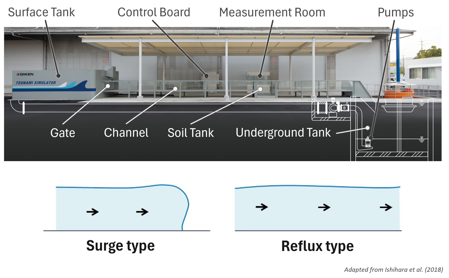
The Tsunami Simulator is an experimental facility designed for model tests to evaluate the performance of structures against tsunamis. It consists of a surface water tank, gate, channel, soil tank for placing model structures, underground water tank, pumps, a control board for pump operation, and a measurement room.
The channel is 19.5 m long, 1.5 m wide, and 0.8 m deep. The soil tank has a length of 1.5 m and extends an additional 0.5 m below the bottom of the channel.
Two types of model tsunamis can be generated: a surge-type wave, representing the leading front of a tsunami, and a reflux-type wave, simulating the main body of the tsunami.
Further details can be found in Ishihara et al. (2018).
Reference
Ishihara, Y., Okada, K. and Hamada, M. 2018. Comparison of pile-type and gravity-type coastal levees in terms of resilience to tsunami. Proceedings of the First International Conference on Press-in Engineering 2018, Kochi, pp. 251-256.
Press-in Experimental Apparatus
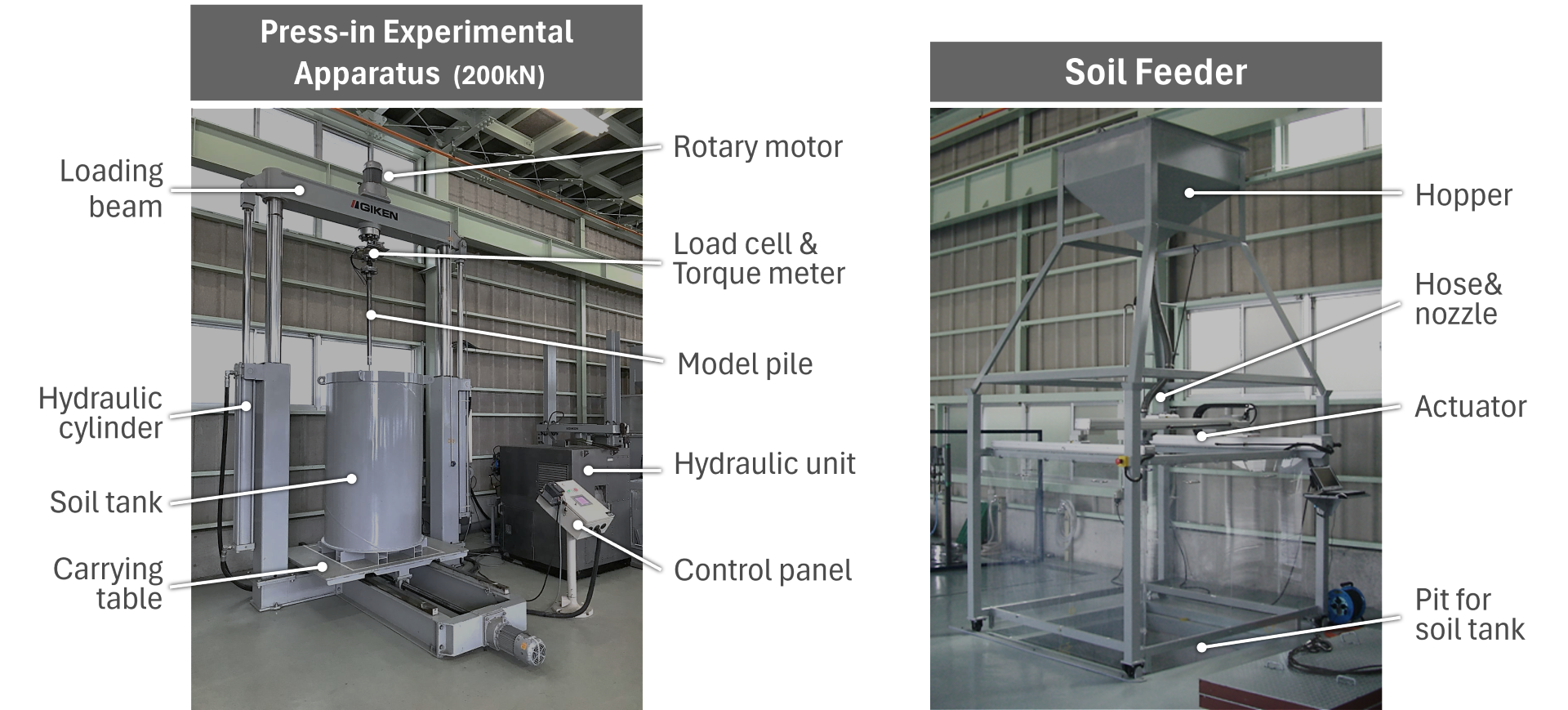
The Press-in Experimental Apparatus is designed for medium-scale model experiments. In this apparatus, a model pile connected to a horizontal loading beam is pressed-in into the model ground within a soil tank by the vertical movement of the loading beam. The motion of the loading beam is generated by hydraulic force applied from a hydraulic unit to a cylinder and is controlled via a control panel. In addition, the model pile can be rotated using a rotary motor to simulate rotary press-in and rotary cutting press-in processes.
The plan shape of the soil tank can be either square or circular. The figure shows a circular soil tank with a diameter of approximately 1 m. To prepare sandy model ground, a device called a Soil Feeder is used. Sand stored in a hopper is delivered into the soil tank through a hose and nozzle using an air pluviation method. The two-dimensional movement of the nozzle can be controlled automatically by an actuator.
Research Building
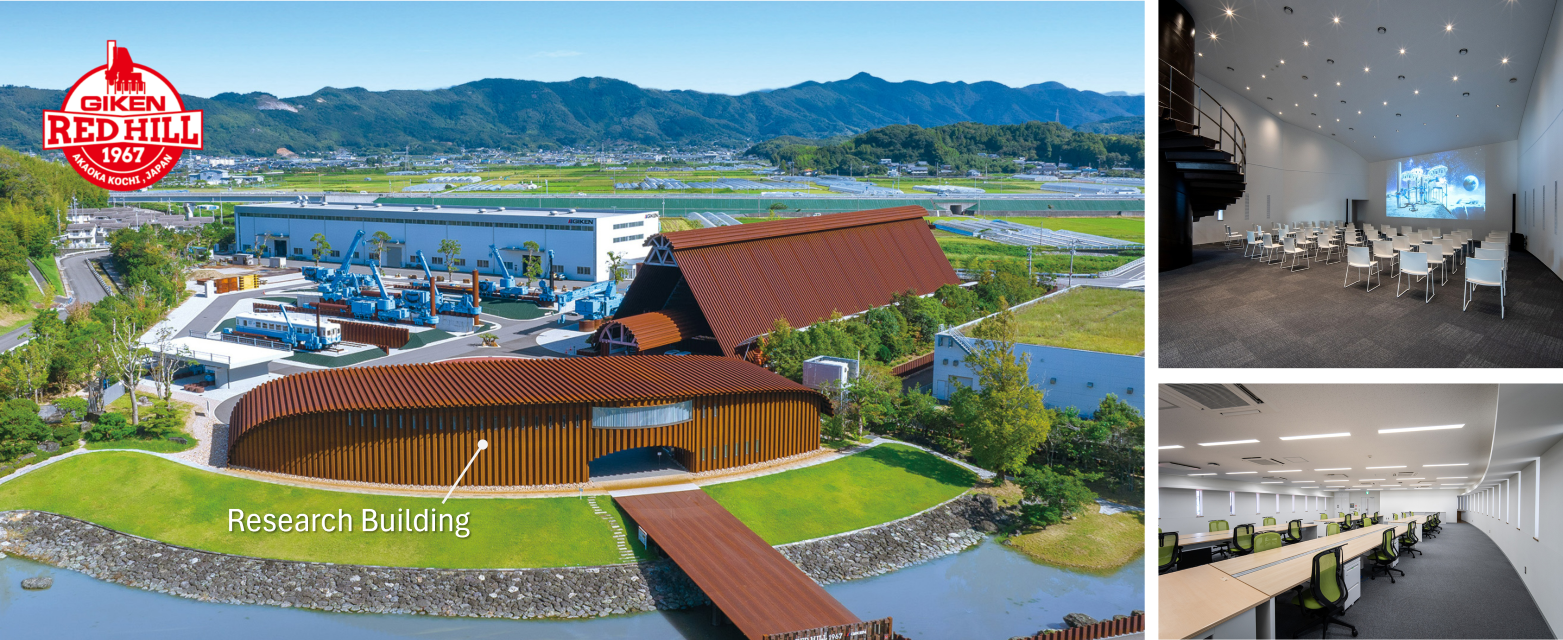
Members of the R&D Center use the Research Building for analysis, discussions, and technical collaboration with external partners. It is a unique structure primarily composed of steel sheet piles. Its foundations and walls are constructed seamlessly using sheet pile walls in the vertical direction, integrating the superstructure and substructure into a single system. Further technical details can be found in Kondo et al. (2023).
The Research Building is located at a site known as RED HILL 1967. This site features an exhibition area showcasing full-scale press-in machines and structures constructed using pressed-in piles, as well as two innovative buildings made of steel sheet piles: the Research Building and the Museum for Piling Machines. The site offers a wide range of information on disaster prevention and mitigation based on a “seeing is believing” concept and welcomes a diverse range of visitors, including families and elementary school students. More information and visitor reservations are available on the website: https://redhill1967.giken.com/en/
Reference
Kondo, Y., Sato, K., Nishimori, Y., Nakagawa, D. (2023). Giken Research Building: challenge for structure using sheet piles (part 2). Steel Technology, pp. 34-43. (in Japanese)
Others
We utilize a variety of additional apparatuses in our R&D activities.
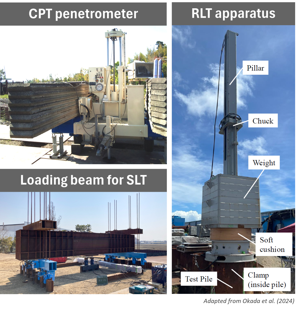
A CPT (Cone Penetration Test) penetrometer is used to install a CPT probe into the ground using static force. This equipment has been employed in full-scale field experiments at GIKEN since the 1980s.
A loading beam for SLT (Static Loading Test) is used to conduct static load tests on piles. Hydraulic jacks and load cells are installed between the loading beam and the test pile to apply and measure vertical static loads.
An RLT (Rapid Loading Test) apparatus is used to perform rapid loading tests on piles. It consists of a pillar, chuck, weight, cushion, and clamp, and can be securely mounted on the test pile via the clamp (Okada et al., 2024). This apparatus eliminates the need for a guide frame to drop the weight onto the pile, thereby preserving the spatial efficiency of press-in piling operations.
Reference
Okada, K., Murata, T., Mori, A., Toda, Y. and Ishihara, Y. 2024. Development of rapid load test device and its applicability to piles installed by Rotary Cutting Press-in. Proceedings of the 3rd International Conference on Press-in Engineering 2024, Singapore, pp. 124-130.